What Should You Check Before IP67 Manual Call Point Cover Placement?
Manual call point cover placement is the process of checking whether a protective enclosure can be positioned around a fire alarm manual call point while maintaining visibility, emergency access, operating clearance, environmental protection and maintenance access.
An IP67 protective cover may look simple on a product drawing. On a real project, however, the wall, door, back box, conduit, device depth and surrounding equipment can completely change whether the installation works.
That is why this IP67 manual call point cover placement guide focuses on what contractors and project buyers should verify before drilling, installation or bulk ordering.
For one alarm point, a placement mistake may mean a few minutes of rework. Across a hotel, warehouse, factory or commercial project with hundreds of devices, the same small mistake can affect installation schedules, labor and product compatibility.
Why Check Manual Call Point Cover Placement Before Installation?
The protective cover normally does not determine where the fire alarm manual call point should be located.
The project fire alarm design and applicable local requirements determine the call point position. The cover is then fitted around that approved position when additional protection is required.
Therefore, good manual call point cover placement starts by asking:
- Is the existing call point position confirmed?
- Is there enough wall space?
- Can the cover open freely?
- Will people still see and reach the device?
- Is the environment suitable for the selected protection?
- Does the complete installed call point physically fit?
This pre-installation check is different from simply asking, “Where should I install the cover?”
It is a site compatibility audit.
1. Confirm the Actual Manual Call Point Position
Before evaluating manual call point cover placement, verify the alarm point shown on the project drawing or already installed on the wall.
Do not move the fire alarm device simply because another wall area makes the enclosure easier to install.
Instead, inspect the surroundings of the approved position.
Look for:
- doors;
- wall corners;
- handrails;
- exit signs;
- access-control readers;
- switches;
- pipes;
- cable trunking;
- other fire alarm devices.
A drawing may show plenty of free wall space, while the completed project may look completely different.
For retrofit projects, front and side photographs provide valuable information before selecting the cover.
2. Measure Width, Height and Projection Depth
Measurements are one of the most important parts of manual call point cover placement.
Do not measure only the visible red face of the call point.
Record the complete installed:
Width – from the left to right edge of the complete assembly.
Height – including any mounting plate or surface box.
Projection depth – from the finished wall surface to the furthest projecting part.
Also include:
- back boxes;
- spacers;
- cable glands;
- mounting plates;
- waterproof adapters;
- raised screws;
- conduit fittings.
Depth is especially easy to underestimate.
A manual call point that appears compact from the front may project much farther after the back box and wiring accessories are installed.
This is why measurement should happen before large orders—not after the covers reach the project.
3. Check Lid Opening Clearance
Correct manual call point cover placement requires more than enough space for the frame.
The transparent lid also needs room to move.
Before drilling, simulate the complete opening movement.
Make sure the lid does not contact:
- a door frame;
- another alarm device;
- wall-mounted signage;
- a handrail;
- conduit;
- a corner;
- an electrical switch;
- an access-control panel.
Hand clearance matters too.
A cover may technically open while leaving such a narrow space that emergency operation becomes awkward.
Protection should add a deliberate physical barrier against accidental contact without turning the alarm point into a difficult device to operate.
4. Test the Door Swing
Doors are a frequent source of installation conflicts.
For manual call point cover placement near exits or stairways, check both the cover movement and the complete door movement.
Open the nearby door fully.
Ask:
Does the door strike the cover?
Does the open door hide the manual call point?
Can the transparent lid still open?
Will a door handle hit the enclosure?
Could the enclosure accidentally become a door stop?
This check is particularly useful in warehouses, hotels, plant rooms, service corridors, parking facilities and emergency exit areas.
A one-minute door test can prevent repeated impact after handover.
5. Evaluate Outdoor and Industrial Exposure
An IP67 cover is often considered where the manual call point faces more demanding environmental conditions.
For outdoor manual call point cover placement, examine the environment rather than relying only on the words “IP67”.
Consider:
- direct rain;
- wind-driven moisture;
- airborne dust;
- cleaning water;
- humidity;
- sunlight;
- debris;
- public contact;
- carts or equipment.
The finished protection also depends on the complete installation, including mounting, seals, cable entry and wall condition.
Therefore, a weatherproof call point cover should be treated as part of the complete installation—not as a shortcut that makes every mounting condition automatically suitable.
6. Check Cable Entry Before Mounting
Wiring direction is often forgotten during manual call point cover placement.
Determine whether the cable or conduit enters from the:
- top;
- bottom;
- side;
- rear.
A surface conduit may interfere with the frame.
A side-entry gland may reduce lid clearance.
A top-entry fitting may require additional wall space.
A rear-entry arrangement depends heavily on mounting surface preparation.
For existing projects, send the supplier a photograph showing the conduit as well as the call point.
That provides much better information than asking whether a cover is “universally compatible.”
7. Avoid High-Impact Zones
Factories, warehouses, car parks and logistics areas create different risks from normal office corridors.
Good manual call point cover placement should consider the movement of:
- pallet trucks;
- forklifts;
- carts;
- ladders;
- cleaning equipment;
- tools;
- stored materials.
A fire alarm protective cover can reduce everyday impact and accidental contact, but it should not be placed directly in a repeated heavy-collision path.
Also think about what happens after installation.
An empty wall during construction may later be blocked by shelving, cartons or equipment.
Review the normal operating environment—not just the construction-stage photograph.
8. Keep the Alarm Point Visible
Protection should not hide the emergency device.
During manual call point cover placement, walk toward the device from the normal approach route.
Check whether:
- the manual call point remains visible;
- its color can be recognized;
- instructions remain readable;
- signs are not obstructed;
- nearby equipment creates confusion.
A transparent enclosure is especially useful because the alarm point remains visible behind the protective barrier.
But transparency alone cannot solve poor placement.
If a rack, door or wall corner blocks the device, the installation still needs review.
9. Inspect the Mounting Surface
The wall itself is part of manual call point cover placement.
Before fixing the enclosure, confirm that the surface is sufficiently:
- flat;
- rigid;
- stable;
- suitable for the fixing method.
Uneven masonry, cladding seams, weak panels or damaged wall surfaces may prevent a clean fit.
Outdoor installations deserve additional attention because poor contact between the enclosure and mounting surface can create unwanted gaps.
Installation teams should therefore check the wall before drilling instead of attempting to correct surface problems after mounting.
10. Leave Space for Inspection and Maintenance
A good installation should remain practical years after commissioning.
Manual call point cover placement should allow technicians to:
- lift the protective lid;
- test the call point;
- access the reset mechanism where applicable;
- inspect the enclosure;
- clean the transparent cover;
- inspect surrounding wiring and accessories.
Avoid placing the cover so tightly between other devices that maintenance requires dismantling neighboring equipment.
For a project with many alarm points, easier maintenance can also reduce future service time.
Manual Call Point Cover Placement Checklist for Projects
Before approval, use this simple checklist:
| Site Check | Information |
|---|---|
| Manual call point model | ______ |
| Width × height | ______ mm |
| Installed depth | ______ mm |
| Back box / spacer | Yes / No |
| Cable entry | Top / Bottom / Side / Rear |
| Lid opens freely | Yes / No |
| Door swing checked | Yes / No |
| Device remains visible | Yes / No |
| Wall condition checked | Yes / No |
| Indoor / outdoor | ______ |
| Impact risk | Low / Medium / High |
| Front photo | Yes / No |
| Side photo | Yes / No |
| Sample verification | Yes / No |
| Project quantity | ______ pcs |
For distributors and system integrators, this information makes supplier communication much more efficient.
How Can Sumring Support Project Compatibility?
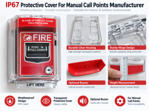
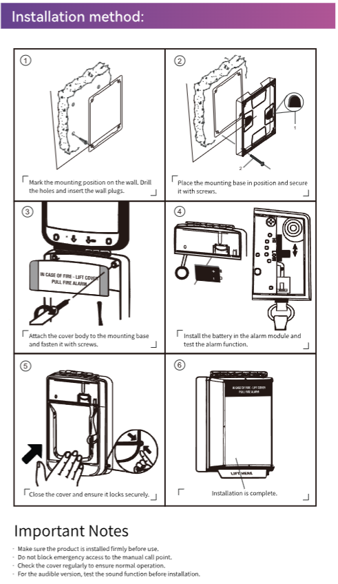
Sumring’s current SR-A08-PS product information lists an IP67 manual call point cover designed for outdoor fire alarm protection, with PC construction, sound and non-sound configurations and ODM customization options.
However, even a cover designed for wide compatibility should be verified against the actual project device.
Before requesting a quotation, buyers can provide:
- manual call point brand and model;
- width;
- height;
- installed projection depth;
- front and side photographs;
- back-box information;
- cable-entry direction;
- required quantity;
- language or marking requirements;
- logo and packaging requirements.
This turns a general inquiry into a project-specific compatibility check.
For non-standard devices or unusual installation spaces, confirming dimensions before mass production is much more efficient than solving fit problems after delivery.
FAQ
1. What is manual call point cover placement?
Manual call point cover placement means checking whether a protective enclosure can fit around the approved alarm point while maintaining visibility, access, clearance and maintainability.
2. Is cover placement the same as choosing the manual call point location?
No. The fire alarm design determines the manual call point location. Cover placement checks whether the protective enclosure works correctly at that location.
3. What dimensions should buyers provide?
Provide complete width, height and installed projection depth, including the back box, spacer, conduit fitting and other accessories.
4. Why is projection depth important?
A device may fit within the cover’s width and height but still prevent the lid from closing if the complete assembly projects too far from the wall.
5. Should door swing be checked?
Yes. Doors can strike, hide or restrict the cover. Test both the door movement and protective lid before fixing the enclosure.
6. Can an IP67 call point cover be used outdoors?
It can suit many outdoor and semi-outdoor applications when the product specification, mounting method, sealing and actual site environment are appropriate.
7. What should B2B buyers send Sumring before ordering?
Send the model, dimensions, installed depth, front/side photos, cable position, application environment, quantity and customization requirements.
8. Is sample testing recommended before bulk purchasing?
For unfamiliar devices, custom installations or high-volume projects, a sample compatibility check can reduce installation and purchasing risk.
Conclusion
Correct manual call point cover placement combines the approved fire alarm position with real device dimensions, opening clearance, door movement, cable routing, wall conditions, environmental exposure and future maintenance.
For one installation, these checks help avoid rework.
For a contractor or distributor purchasing hundreds of covers, they can prevent a site-wide compatibility problem.
So before comparing only unit prices, prepare four basic pieces of information:
front photo + side photo + width/height + installed projection depth.
Then add the cable-entry direction and project quantity.
Send these details to Sumring before bulk ordering or requesting a customized cover.
A few minutes of placement verification before production can save an entire project from installation rework later.